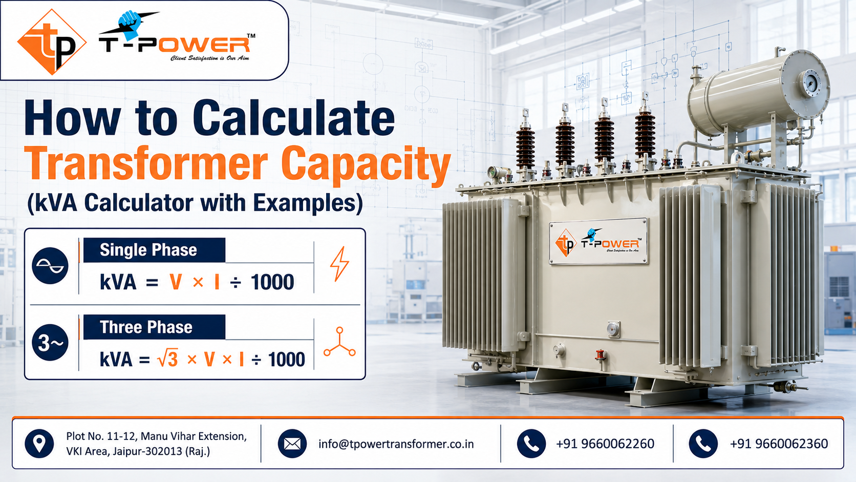
How to Calculate Transformer Capacity (kVA Calculator with Examples) – 2026 Guide
Selecting a transformer begins with a simple question: how much electrical load must it supply? The answer is expressed in kilovolt-amperes (kVA), but an accurate selection requires more than adding the kilowatts printed on equipment nameplates. Voltage, current, phase, power factor, efficiency, demand, diversity, motor starting, harmonics, ambient temperature, altitude and future expansion can all change the correct rating.
This detailed 2026 guide explains How to Calculate Transformer Capacity (kVA Calculator with Examples) for factories, commercial buildings, renewable-energy plants, infrastructure projects and replacement installations. It includes single-phase and three-phase formulas, an interactive calculator, worked examples, a load-schedule method and a practical engineering itinerary. The calculator provides a preliminary estimate; the final transformer must be verified against the complete system study and approved technical specification.
T Power Transformer designs and manufactures application-specific transformer solutions. When a project involves motors, nonlinear loads, inverter duty, unusual voltage ratios, high ambient temperature or special impedance, sharing the complete load and system data helps the engineering team select a safer and more economical design.
Quick Answer: Transformer kVA Calculation Formulas
Use the formula that matches the information available. Voltage should be entered in volts, current in amperes and active power in kilowatts.
| Known Data | Formula | Important Note |
|---|---|---|
| Single-phase voltage and current | kVA = V × I ÷ 1000 | Use the voltage across the single-phase load. |
| Three-phase line voltage and line current | kVA = √3 × V × I ÷ 1000 | Use line-to-line voltage and line current. |
| Load kW and power factor | kVA = kW ÷ PF | PF is entered as a decimal, such as 0.90. |
| Motor shaft kW, efficiency and PF | kVA = motor kW ÷ (efficiency × PF) | This estimates running input kVA, not starting duty. |
| Known kVA and single-phase voltage | I = kVA × 1000 ÷ V | Useful for estimating full-load current. |
| Known kVA and three-phase voltage | I = kVA × 1000 ÷ (√3 × V) | Gives approximate line current at rated kVA. |
Important: do not multiply the three-phase formula by power factor when calculating kVA from measured voltage and current. The expression √3 × V × I already gives apparent power. Power factor is used when converting between kW and kVA.
Interactive Transformer kVA Calculator
The calculator below provides a quick preliminary result. Choose the calculation method, enter positive values and add only a project-justified margin. A 15% or 20% allowance is not a universal rule; the appropriate reserve depends on measured demand, load growth, duty cycle, operating philosophy and applicable design criteria.
If your website editor removes JavaScript, the formulas and examples in the remaining article still work as a manual transformer capacity calculator. The interactive result should never be interpreted as a purchase specification by itself.
What Does Transformer Capacity in kVA Mean?
A transformer transfers alternating-current power between voltage levels through electromagnetic induction. Its rating is generally stated in kVA because the thermal burden on the windings and insulation is related mainly to voltage and current. Copper or winding loss is influenced by current, while core loss is primarily associated with applied voltage and frequency. The transformer must carry apparent power even when the connected load converts only part of it into useful active power.
Active power, measured in kilowatts, performs useful work such as turning a motor shaft, heating a process or powering electronic equipment. Reactive power, measured in kVAr, supports magnetic and electric fields. Apparent power, measured in kVA, is the combined electrical burden. In a simplified sinusoidal system:
kVA² = kW² + kVAr²
Power factor is the ratio of active power to apparent power:
PF = kW ÷ kVA, therefore kVA = kW ÷ PF.
A 100 kW load operating at 1.0 power factor requires 100 kVA. The same 100 kW load at 0.80 power factor requires 125 kVA. This is why sizing a transformer from kW alone can underestimate current and heating. For distorted current from nonlinear equipment, displacement power factor alone may not describe the total burden; true power factor and harmonic data should be considered.
Rated kVA Is Not the Same as Energy Consumption
Capacity and energy are different. A 500 kVA transformer is capable of supplying a defined apparent-power load under its rated conditions. It does not continuously consume 500 kVA. Energy billing is based on use over time and may include kWh, kVAh, maximum-demand or reactive-energy components depending on the tariff. Transformer losses also vary between the continuously present no-load loss and current-dependent load loss.
Why Nameplate Conditions Matter
The rated power assumes specified voltage, frequency, cooling, temperature-rise and service conditions. High ambient temperature, high altitude, restricted ventilation, unusual harmonics or frequent overload may require derating or a design adapted to the application. In 2026 procurement, rating should therefore be evaluated alongside the applicable standard, environmental data and duty profile—not as an isolated number.
Data Required Before You Calculate Transformer Capacity
A reliable calculation begins with a load schedule and single-line diagram. Collect the following information before choosing a rating:
- Incoming and outgoing nominal voltage, system maximum voltage and frequency.
- Single-phase or three-phase supply and proposed winding connection or vector group.
- Installed kW, kVA or current for every major load.
- Power factor and efficiency at realistic operating load, not only an assumed value.
- Demand factor, diversity, duty cycle and simultaneous operating combinations.
- Largest motor rating, starting current, starting method and permitted voltage dip.
- Harmonic spectrum or total harmonic distortion for VFDs, UPS systems, rectifiers and inverters.
- Continuous, cyclic, intermittent, standby or emergency operating duty.
- Maximum and minimum ambient temperature, altitude, indoor/outdoor location and ventilation.
- Short-circuit level, required transformer impedance and protection coordination.
- Future loads that are funded or reasonably planned, with their expected commissioning date.
- Reliability philosophy: one transformer, duty/standby, or parallel units under N-1 operation.
Do not simply add every connected nameplate load and then add a large arbitrary margin. That approach can produce an oversized transformer with higher capital cost, larger footprint and avoidable no-load losses. The opposite mistake—using only a recent maximum-demand value without allowing for motor starting, seasonal peaks or expansion—can create overheating and voltage-performance problems.
Single-Phase Transformer Capacity Calculation
For a single-phase circuit:
Transformer kVA = Voltage × Current ÷ 1000
Example 1: Single-Phase Load From Voltage and Current
A facility needs a 230 V single-phase transformer for equipment drawing 80 A at maximum continuous operation.
kVA = 230 × 80 ÷ 1000 = 18.4 kVA.
If the documented design basis permits a 20% reserve for near-term additions:
Design requirement = 18.4 × 1.20 = 22.08 kVA.
A 25 kVA rating may appear suitable, subject to voltage ratio, load type, temperature, harmonic content, starting duty and availability. The calculation does not mean that 25 kVA is automatically correct for every 18.4 kVA load.
Example 2: Single-Phase Current Available From a 50 kVA Unit
For a 50 kVA, 415 V single-phase secondary:
I = 50 × 1000 ÷ 415 = 120.48 A.
Protection and cable selection must still follow the applicable rules, installation method, coordination study and permitted operating conditions. Transformer full-load current is an input to those studies, not a substitute for them.
Three-Phase Transformer Capacity Calculation
For a balanced three-phase circuit using line-to-line voltage:
Transformer kVA = 1.732 × Line Voltage × Line Current ÷ 1000
The factor 1.732 is the approximate value of √3. Use line voltage and line current consistently. Do not insert phase-to-neutral voltage into this formula unless you are deliberately reformulating the calculation.
Example 3: Three-Phase Industrial Load
A 415 V three-phase load draws 250 A at its expected peak operating condition.
kVA = 1.732 × 415 × 250 ÷ 1000 = 179.70 kVA.
If load records are reliable and a justified reserve leads to a requirement below 200 kVA, a 200 kVA transformer could be evaluated. However, the engineer must check phase imbalance, nonlinear current, peak duration, motor acceleration and environmental conditions before confirming the selection.
Example 4: Full-Load Current of a 1000 kVA Transformer
For a 1000 kVA three-phase transformer with an 11 kV primary:
Primary current = 1000 × 1000 ÷ (1.732 × 11,000) = 52.49 A.
For a 433 V secondary:
Secondary current = 1000 × 1000 ÷ (1.732 × 433) = 1,333.45 A.
These currents are approximate rated line currents. The detailed design must address tapping, tolerances, impedance, temperature and system operating voltage.
Calculating kVA From kW and Power Factor
When a load schedule provides active power in kW, convert each load or coherent load group into kVA using its power factor:
kVA = kW ÷ Power Factor
Example 5: 180 kW Process Load
A process line has a maximum coincident input demand of 180 kW at a true power factor of 0.90.
Required running apparent power = 180 ÷ 0.90 = 200 kVA.
If the approved growth allowance is 20%, the planning value becomes 240 kVA. A 250 kVA transformer might be shortlisted, but only after verifying the load waveform, starting events and service conditions.
Why Correct Power Factor Data Matters
If the actual power factor falls to 0.80, the same 180 kW requires 225 kVA. Power-factor correction can reduce current on the upstream system when it is correctly engineered, but capacitors must not be treated as a shortcut without harmonic-resonance and switching review. In facilities with variable-speed drives, UPS systems or solar inverters, the designer should use equipment data and measurements that reflect true power factor across the intended operating range.
Motor Load Transformer Calculation
Motor nameplates commonly show mechanical output in kW. Transformer input must account for motor efficiency and power factor:
Running kVA = Motor Output kW ÷ (Efficiency × Power Factor)
Example 6: 75 kW Motor
Consider a 75 kW motor with 93% efficiency and 0.86 power factor at the relevant load point.
Running kVA = 75 ÷ (0.93 × 0.86) = 93.79 kVA.
This is the running demand. It does not represent the starting demand. A direct-on-line induction motor can draw several times rated current during acceleration. If an illustrative starting-current multiple of six were applied, the transient apparent power would be approximately 563 kVA. It would be incorrect to select a 630 kVA transformer from that multiplication alone. Starting duration, transformer impedance, upstream source strength, cable impedance, load torque, permissible voltage dip, other connected loads and motor protection must be modelled.
A star-delta starter, soft starter or variable-frequency drive may reduce or reshape the starting current, but each has application constraints. The transformer designer needs the starter type and manufacturer data. A VFD also introduces nonlinear loading, so harmonic heating and waveform effects require review.
Multiple Motors
For several motors, calculate the expected coincident running kVA, then assess the worst credible starting sequence. If the largest motor starts while the others are operating, use that operating state in the voltage-dip study. If process controls guarantee sequential starting, document the interlock rather than relying on an informal operating practice.
Industrial Load-Schedule Example
The most useful method for a factory or commercial project is a transparent load schedule. The example below treats listed kW as electrical input demand before applying the stated demand factor.
| Load Group | Connected kW | Demand Factor | Demand kW | Power Factor | Demand kVA |
|---|---|---|---|---|---|
| Lighting and small power | 50 | 0.90 | 45 | 0.95 | 47.37 |
| Process motors | 200 | 0.75 | 150 | 0.88 | 170.45 |
| HVAC plant | 120 | 0.80 | 96 | 0.90 | 106.67 |
| UPS and data load | 80 | 1.00 | 80 | 0.95 | 84.21 |
| Workshop and miscellaneous | 40 | 0.60 | 24 | 0.90 | 26.67 |
| Total | 490 | — | 395 | — | 435.37 |
If a documented 15% planning reserve is applied, the design value becomes:
435.37 × 1.15 = 500.68 kVA.
This result sits just above 500 kVA, so an engineer should not automatically round down. The load assumptions could be refined through measurements, operating scenarios and future plans, or the next suitable rating could be assessed. The decision must also include the largest motor start, harmonic duty, permissible temperature rise, redundancy and available ratings. A load table is valuable because every assumption can be challenged and updated.
Demand Factor vs Diversity Factor
Demand factor is maximum demand divided by total connected load and is normally no greater than one. Diversity recognises that individual peaks do not always occur together; definitions and calculation conventions can vary by organisation. To avoid double counting, state exactly how each factor was derived. Historical interval-meter data is generally more persuasive than a generic percentage copied from another project.
Solar and Inverter Duty Transformer Capacity
A solar transformer is often selected from the combined AC output capability of connected inverters, but the calculation must consider the full grid-code operating envelope. At unity power factor, eight 250 kW inverter blocks have a nominal combined output of 2,000 kVA. If the plant must deliver the same active power while operating at 0.95 power factor, the apparent power becomes:
2,000 kW ÷ 0.95 = 2,105.26 kVA.
This does not by itself establish the final transformer rating. The EPC and manufacturer should review inverter maximum current, reactive-power requirement, clipping strategy, overload capability, number of LV windings, harmonic spectrum, switching frequency effects, DC injection limits, daily thermal cycling, site ambient temperature, altitude, cable loading and plant availability philosophy.
For inverter duty, a transformer that is adequate by fundamental-frequency kVA can still require additional thermal attention because harmonic currents increase stray and winding losses. The correct design uses inverter data and the applicable project specification. Do not apply a generic “solar derating percentage” without an engineering basis.
Nonlinear Loads, Harmonics and K-Factor Considerations
UPS systems, rectifiers, variable-frequency drives, LED drivers, data equipment, welders and power-electronic converters can draw nonsinusoidal current. RMS current determines conductor heating, but higher-frequency harmonic components can create additional eddy-current and stray losses. Triplen harmonics in four-wire systems can accumulate in the neutral rather than cancel.
A conventional kVA calculation remains the starting point, not the complete answer. Collect the current spectrum, total harmonic distortion, crest factor, load duty and neutral-current information. Depending on transformer type and governing requirements, the solution may involve a specifically designed transformer, electrostatic shielding, winding arrangement, enhanced thermal design, neutral sizing or harmonic mitigation. “K-factor” terminology is common for certain dry-type applications, but it must be applied within the relevant product and standard context rather than added as a marketing label.
How Much Spare Capacity Should You Add?
Many online guides recommend adding 20% or 25% to every calculation. A reserve can be sensible, but a universal figure is not an engineering rule. Use a margin that corresponds to identifiable uncertainty and growth.
- Measurement uncertainty: incomplete meter history or variable production schedules may justify a documented allowance.
- Approved expansion: include equipment that has a realistic installation plan, not speculative future load.
- Cyclic peaks: evaluate duration and thermal response instead of treating every short peak as continuous.
- Motor starting: study voltage dip and acceleration separately rather than hiding the event inside a percentage.
- Redundancy: under N-1 operation, each remaining transformer may need to carry more load for a defined period.
- Economic loading: compare lifecycle losses and utilisation, not just the smallest rating that passes the peak.
Oversizing can reduce load loss at a given demand but increases purchase cost, footprint and the no-load loss associated with energising a larger core. Undersizing increases temperature, reduces voltage quality and may accelerate insulation ageing. The optimum selection balances load profile, loss capitalisation, reliability and expansion.
2026 Transformer Selection Itinerary: From Load Survey to Commissioning
This step-by-step itinerary turns a calculator result into a procurement-ready transformer specification.
Step 1: Create a Verified Load List
Record every major load with voltage, phase, kW or current, power factor, efficiency, duty and starting method. Separate existing, approved future and speculative loads.
Step 2: Build Operating Scenarios
Define normal production, maximum production, night operation, maintenance, emergency and future-expansion states. Identify which loads can truly operate together.
Step 3: Use Meter Data Where Available
Review interval demand, current, power factor, harmonic and seasonal data. Confirm instrument scaling and investigate abnormal peaks before using them as design values.
Step 4: Calculate Running kVA
Use V × I for single-phase loads, √3 × V × I for three-phase loads, or kW ÷ PF when active power is known. Apply efficiency when motor data represents mechanical output.
Step 5: Apply Demand and Diversity Transparently
Document the source of every factor and avoid applying several overlapping reductions. Preserve the spreadsheet or calculation sheet for design review.
Step 6: Check the Largest Disturbance
Study motor starting, transformer energisation, welding cycles, furnace duty, inverter operation and step-load events. Confirm the permitted voltage dip and protection behaviour.
Step 7: Review Harmonic and Phase-Unbalance Duty
Provide waveform or equipment data for nonlinear loads. Balance single-phase circuits across the three phases and assess neutral loading where relevant.
Step 8: Add Justified Growth and Reliability Capacity
Include committed expansion and N-1 requirements with dates and operating duration. Avoid repeating the same allowance in both the demand factor and final margin.
Step 9: Define Site and System Conditions
Specify voltage, frequency, insulation level, altitude, ambient temperature, pollution, indoor/outdoor installation, enclosure, cooling, impedance, short-circuit level and earthing.
Step 10: Select Construction and Accessories
Evaluate liquid-immersed or dry-type construction, conductor material, tapping method, protection devices, temperature indication, marshalling, communication and monitoring according to application risk.
Step 11: Compare Available Ratings and Lifecycle Cost
Compare guaranteed losses at the expected load profile, not only purchase price. Check dimensions, transport mass, cable or bus-duct current and substation layout.
Step 12: Obtain Manufacturer Design Review
Send the single-line diagram, load schedule, harmonic data and specification to the manufacturer. Resolve assumptions and deviations before purchase.
Step 13: Approve Drawings and Test Plan
Review guaranteed technical particulars, general arrangement, terminals, foundation loads, schematic, nameplate and inspection plan. State applicable standards and acceptance criteria precisely.
Step 14: Inspect, Install and Commission
Verify transport condition, assembly, fluid or insulation condition as applicable, earthing, terminations, protection settings and pre-energisation tests. Follow approved procedures and qualified supervision.
Step 15: Validate the Real Load
After commissioning, trend phase currents, voltage, kW, kVA, power factor and temperature under representative operations. Update the load register before adding major equipment.
Common Transformer Capacity Calculation Mistakes
- Using kW as kVA: this ignores power factor and can underestimate current.
- Multiplying kVA by power factor twice: V × I already gives apparent power.
- Using 230 V in the three-phase formula for a 415 V line-to-line system: inconsistent voltage creates a wrong result.
- Ignoring motor efficiency: shaft output is lower than electrical input.
- Treating starting kVA as continuous kVA: motor acceleration needs a voltage-dip and dynamic-duty assessment.
- Adding every nameplate load at 100%: this may overstate realistic maximum demand.
- Applying unsupported diversity: an optimistic factor can hide a real overload.
- Ignoring harmonics: nonlinear loads may create extra thermal stress.
- Ignoring ambient and altitude: cooling capability depends on the installation environment.
- Rounding down to the nearest catalogue rating: a calculated requirement above a rating needs refinement or the next suitable option.
- Choosing only by kVA: voltage ratio, vector group, impedance, insulation, tapping and protection are equally essential.
- Assuming spare capacity equals future readiness: switchgear, cables, ventilation and utility capacity must also support expansion.
Capacity Is Only One Part of Transformer Selection
Two transformers with the same kVA may be unsuitable substitutes. The final specification should cover primary and secondary voltage, highest system voltage, frequency, phases, vector group, impedance, tap range, off-circuit or on-load tap changer, insulation level, cooling method, winding material, temperature rise, guaranteed losses, sound requirement, enclosure or tank arrangement, terminal interfaces and accessories.
Impedance affects fault current, voltage regulation and parallel operation. A lower impedance can improve voltage drop but increases prospective fault current. A higher impedance limits fault current but can worsen voltage dip during motor starting. The value must coordinate with the network rather than being selected in isolation.
For parallel transformers, voltage ratio, tap position, polarity, phase sequence, vector group, impedance and other operating characteristics must be compatible. Load sharing and circulating current should be studied. Do not assume that equal kVA ratings guarantee successful parallel operation.
Standards and Engineering Verification in 2026
The IEC 60076 family provides internationally recognised requirements for power transformers, while the IS 2026 series is central to power-transformer standards in India. The applicable part, edition and project clauses depend on transformer type and duty. For example, IEC 60076-7 provides loading guidance for mineral-oil-immersed transformers from the perspective of operating temperature and thermal ageing, and IEC 60076-11 addresses specified categories of dry-type transformers.
A capacity calculator does not confirm compliance with a standard. The purchaser and manufacturer should agree on service conditions, rating basis, tests, tolerances, guaranteed losses and documentation. Utility rules, electrical-safety requirements, local regulations and consultant specifications may add obligations beyond a general transformer standard.
Where project consequences are significant, use a qualified electrical engineer to validate load flow, motor starting, short-circuit level, protection coordination, arc-flash risk, harmonics, earthing and cable or bus-duct selection. This article is an educational calculation guide, not a substitute for project-specific engineering approval.
Frequently Asked Questions
1. What is the formula for transformer capacity in kVA?
For single phase, kVA = V × I ÷ 1000. For three phase, kVA = √3 × line voltage × line current ÷ 1000. When kW and power factor are known, kVA = kW ÷ PF.
2. How do I convert 100 kW to kVA?
Divide by power factor. At 0.80 PF, 100 kW equals 125 kVA. At 0.95 PF, it equals approximately 105.26 kVA. Use the actual or specified true power factor.
3. What size transformer is required for a 200 kW load?
The answer depends on power factor, demand, starting duty and design reserve. At 0.90 PF, 200 kW is 222.22 kVA before any justified allowance. A manufacturer or engineer should validate the next suitable rating and full specification.
4. Should I add 20% spare capacity?
Only if 20% reflects documented growth or uncertainty. There is no universal margin for every project. Consider measured demand, expansion, cyclic load, redundancy, losses and available ratings.
5. Can I size a transformer using amperes only?
You also need voltage and phase. For three-phase systems, confirm whether the stated voltage is line-to-line and whether current is the maximum coincident RMS line current.
6. Does power factor affect transformer kVA?
Yes. For a fixed kW load, lower power factor means higher kVA and current. If kVA is calculated directly from measured RMS voltage and current, do not apply PF again.
7. How is transformer size calculated for motors?
Calculate running input kVA from motor output kW divided by efficiency and power factor. Then perform a separate starting study using motor, starter, transformer, cable and source data.
8. Is the next higher standard kVA always the correct choice?
It is a common shortlist approach, but the final choice depends on available ratings, duty, environment, harmonics, voltage performance, losses and system design. Never round down without resolving the deficit.
9. Can one transformer serve both three-phase and single-phase loads?
Often yes, when the secondary connection and neutral arrangement support them. Single-phase loads should be distributed to limit phase imbalance, and neutral current and harmonics require review.
10. How do I size an inverter duty transformer?
Start with total inverter AC output kVA across the required active and reactive operating range. Then review maximum current, overload, harmonics, winding configuration, thermal cycling, ambient temperature, altitude and grid requirements.
11. Is a larger transformer always more efficient?
No. A larger unit may have lower load loss at the same demand but can carry greater no-load loss and capital cost. Compare guaranteed losses across the actual annual load profile.
12. What information should I send a transformer manufacturer?
Send the single-line diagram, load schedule, voltage and frequency, kVA calculation, largest motor data, harmonic information, site conditions, impedance and fault requirements, tapping, vector group, installation details, accessories, standards and test scope.
Why Consult T Power Transformer?
A calculator establishes a starting value; a dependable transformer requires application engineering. T Power Transformer can review project data for distribution transformers, power transformers, industrial units and inverter-duty applications. The objective is to align rating, voltage ratio, impedance, cooling, insulation, losses, tapping, construction and accessories with the actual duty.
For a more useful technical discussion, share the load schedule, single-line diagram, present maximum demand, planned expansion, motor-starting details, inverter or harmonic data and site environment. Clear inputs reduce assumptions and help produce a technically comparable offer.
Need help calculating transformer capacity for your 2026 project? Contact T Power Transformer for an application-specific review and transformer proposal.
- Address: Plot No. 11-12, Manu Vihar Extension, VKI Area, Jaipur – 302013, Rajasthan, India
- Email: info@tpowertransformer.co.in
- Phone: +91 9660062260, +91 9660062360
- Website: www.tpowertransformer.co.in
Conclusion
The correct answer to How to Calculate Transformer Capacity (kVA Calculator with Examples) begins with the right formula and ends with a verified engineering specification. Single-phase kVA equals voltage multiplied by current divided by 1000. Three-phase kVA equals √3 multiplied by line voltage and line current divided by 1000. When kW is known, divide it by power factor; for motor shaft output, also account for efficiency.
Accurate sizing then requires a realistic load schedule, demand and diversity review, motor-starting assessment, harmonic study, environmental conditions, growth plan and reliability strategy. Avoid both blind oversizing and optimistic undersizing. Use the interactive calculator for preliminary planning, document every assumption and involve the transformer manufacturer and qualified system engineer before final approval. That disciplined process produces a transformer selection that is safer, more efficient and better prepared for the operating realities of 2026.
Disclaimer: Calculations and examples are educational and simplified. Final transformer selection, protection and installation must be completed or approved by qualified professionals using the applicable standards, regulations, utility requirements and manufacturer data.

