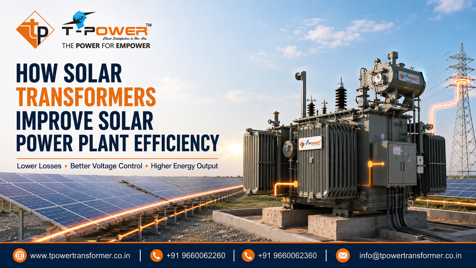
How Solar Transformers Improve the Efficiency of Solar Power Plants
A solar power plant is only as efficient as the complete electrical path that carries energy from photovoltaic modules to the grid or the connected load. Solar panels receive most of the attention, and inverters are often treated as the centre of the plant, but the transformer between the inverter output and the collection or grid network has an equally important responsibility. It must raise voltage, control losses, tolerate inverter-generated electrical stresses, maintain insulation integrity and operate reliably through thousands of daily heating and cooling cycles.
When a transformer is selected only by its kVA or MVA rating, important opportunities can be missed. An unsuitable unit may introduce avoidable no-load and load losses, run hotter than expected, create excessive voltage drop, respond poorly to harmonics or require curtailment during high-temperature periods. A correctly engineered solar transformer reduces those risks. It supports efficient energy transfer during bright midday generation, remains economical during low-output hours and gives the plant operator useful information for timely maintenance.
This 2026 guide from T Power Transformer explains how solar transformers improve the efficiency of solar power plants in practical engineering terms. It is intended for solar developers, EPC contractors, electrical consultants, captive power users, utility teams, O&M professionals and procurement managers. It also shows why efficiency must be evaluated as a lifecycle result rather than a single percentage printed on a data sheet.
What Is a Solar Transformer?
A solar transformer is a power transformer designed or selected for service within a photovoltaic generation system. Its most common function is to step up the alternating-current voltage produced by one or more solar inverters to the medium-voltage or high-voltage level used by the plant collection system. Depending on project architecture, there may also be auxiliary transformers, station transformers, earthing transformers and a larger power transformer at the pooling substation.
The term “solar transformer” does not describe one universal construction. A utility-scale plant may use inverter duty transformers located beside inverter stations, followed by a main power transformer at the pooling point. A rooftop or commercial solar installation may use a compact dry type or oil immersed unit connected to an existing facility network. A hybrid project that combines solar, battery storage and another generation source may impose bidirectional power flow, changing reactive-power requirements and a more complex operating profile.
What distinguishes the application is the duty. Solar inverters create a different electrical and thermal environment from a conventional steady industrial load. The transformer may experience harmonic currents, rapid irradiance changes, repeated energization, long periods at light load, strong midday peaks, high outdoor ambient temperature and a large number of daily thermal cycles. These conditions must be communicated to the manufacturer so that the winding, core, insulation, cooling arrangement, impedance, shielding and accessories can be designed as one coordinated system.
Where Does Energy Get Lost in a Solar Power Plant?
Before understanding the transformer’s contribution, it helps to see the complete energy path. Sunlight is converted to DC electricity by PV modules. DC cables carry that power to string or central inverters. The inverter converts DC to AC. An inverter duty transformer raises the voltage for efficient collection, and the collection network transports power to the pooling substation. A main transformer may then raise voltage again for grid export. Every conversion and every conductor introduces some loss.
Transformer losses are not the only plant losses, but they deserve attention because a transformer can remain energized for long periods and may serve for decades. Even a modest improvement in guaranteed losses can accumulate into meaningful additional export over the asset life. The U.S. Department of Energy similarly notes that transformers operate continuously for long service periods, making small efficiency improvements valuable at system scale. For a solar project, the economic impact depends on the plant load profile, energy tariff, expected generation, degradation, availability and service life.
The main transformer-related loss categories are:
- No-load or core losses: These occur whenever rated voltage is applied, even when the solar plant is producing little or no active power.
- Load or winding losses: These are mainly caused by current flowing through winding resistance and increase strongly as current rises.
- Stray and eddy-current losses: Leakage flux and harmonic content can create additional heating in conductors, structural parts, tank surfaces and other metallic components.
- Cooling-system consumption: Fans, pumps or auxiliary controls consume energy when fitted and operating.
- System losses influenced by the transformer: Poor voltage matching, unsuitable impedance, long low-voltage cable routes or incorrect reactive-power strategy can raise losses beyond the transformer itself.
Therefore, improving solar efficiency is not simply a matter of asking for the lowest possible loss number. The design must balance core loss, copper or aluminium conductor loss, temperature rise, dimensions, fault withstand, cost and the actual hourly generation profile.
How Solar Transformers Improve the Efficiency of Solar Power Plants
1. They Reduce No-Load Losses During Low-Generation Hours
No-load loss is produced in the magnetic core when the transformer is energized. It remains relatively independent of output current, which makes it especially important for solar plants. A PV plant does not generate at rated output for twenty-four hours. It ramps up after sunrise, reaches higher output near the strongest irradiance period, ramps down in the evening and may remain energized overnight depending on the electrical arrangement and operating philosophy.
A low-loss core built with suitable magnetic material, correct flux density, precise joint construction and controlled manufacturing can reduce continuous magnetizing losses. The best design point depends on whether the transformer stays energized at night, how many hours it operates at low load and whether switching it out of service is operationally acceptable. A plant with long energized standby periods may place greater economic value on core-loss reduction than a plant that reliably de-energizes its inverter transformers after generation stops.
The procurement team should request guaranteed no-load losses rather than accepting broad claims such as “energy efficient.” Bid evaluation should calculate the annual cost of those losses using the expected energization hours. This turns an engineering specification into a measurable commercial decision.
2. They Minimise Winding Losses at Peak Solar Output
Load loss is closely related to the square of current. When current increases, winding heating rises rapidly. Solar transformers often operate at low or moderate load during morning and evening, but high output can continue for several hours under favourable conditions. A winding designed with an appropriate conductor cross-section, current density, transposition, cooling path and joint quality lowers resistive loss and controls hot-spot temperature.
The transformer should not be oversized without analysis. Oversizing may reduce the percentage loading and some load losses, but it can increase equipment cost and leave a larger core energized at light load. Undersizing is more dangerous because it raises current density, temperature and ageing while increasing the likelihood of output limitation. The economical rating is the one that gives the lowest lifecycle cost for the expected generation profile, not automatically the largest unit that fits the budget.
3. They Match Inverter Voltage to the Collection Network
Solar inverters typically produce power at a lower AC voltage than the medium-voltage collection system or grid connection. A step-up transformer makes long-distance transport practical by raising voltage and reducing current for the same power transfer. Lower current allows cable losses to fall because conductor loss is proportional to current squared. It can also reduce the required conductor size, voltage drop and the number of parallel low-voltage cable runs.
The benefit depends on correct system architecture. Transformer placement near the inverter reduces the length of high-current low-voltage cable. Coordinated secondary voltage, primary voltage and tap range help the inverter remain within its allowable operating window. If the ratio is poorly selected, the plant may encounter high-voltage trips during strong generation or inadequate voltage support under other grid conditions.
4. They Control Voltage Drop Through Appropriate Impedance
Transformer impedance influences voltage regulation, fault current and parallel operation. Excessive impedance can create avoidable voltage drop and reactive demand at high output. Very low impedance can increase short-circuit current and impose greater duty on switchgear and transformer windings. The correct value must come from a system study that includes inverter characteristics, cable impedance, grid strength, protection settings and utility requirements.
For plants with multiple transformers operating in parallel, matching voltage ratio, vector group, phase displacement and impedance is essential for stable load sharing. Circulating current between mismatched units wastes energy and creates heating without delivering useful power. Careful specification and factory verification prevent that loss mechanism.
5. They Are Designed for Harmonic-Rich Inverter Duty
Modern inverters use high-frequency switching and filters to produce an AC waveform suitable for the network. Although inverter output quality is controlled, residual harmonic components and high-frequency effects can still influence transformer heating. Harmonic currents increase eddy-current and stray losses and may produce local hot spots if a conventional transformer is applied without duty review.
An inverter duty design considers the harmonic spectrum supplied by the inverter manufacturer or system study. Engineering measures may include suitable winding conductor arrangement, electrostatic shielding where required, controlled flux density, insulation coordination, attention to stray-flux paths and an appropriate thermal margin. The goal is not to “block all harmonics” with the transformer. It is to ensure that the transformer operates within safe temperature limits and does not turn waveform distortion into excessive heat and lost energy.
6. They Maintain Efficiency in High Ambient Temperatures
Many solar plants are built in locations with strong sunlight, dust and high ambient temperature. Those are excellent conditions for generation but demanding conditions for electrical equipment. A transformer operating in hotter air has less thermal margin. If the radiator area, oil circulation, enclosure ventilation or cooling controls are inadequate, winding temperature rises and insulation ages faster.
A site-specific design uses actual maximum and average ambient temperature, altitude, solar radiation exposure and duty cycle. Adequate radiator surface, suitable fluid circulation, thoughtful equipment orientation and reliable fan control help the transformer transfer heat efficiently. Lower operating temperature also reduces winding resistance compared with an overheated condition, which helps limit load loss. For dry type installations, ventilation openings and enclosure design must prevent recirculation of hot air.
7. They Support Stable Reactive-Power and Voltage Performance
Solar inverters may be required to supply or absorb reactive power to support grid voltage. The transformer carries the resulting current even when that current does not represent exported active energy. Poor coordination can consume thermal capacity and increase losses. Transformer rating, impedance, tap setting and inverter control philosophy therefore need to be considered together.
A suitable transformer helps maintain voltage at the inverter terminals while meeting point-of-connection requirements. Off-circuit taps can provide commissioning flexibility where the network voltage is predictable. On-load tap changing may be considered for particular main-transformer or pooling-station applications after system analysis. The objective is stable plant operation without unnecessary circulating reactive current or avoidable curtailment.
8. They Reduce Curtailment and Unplanned Downtime
Efficiency is often discussed only as electrical loss, but plant owners earn from energy actually delivered. A transformer that trips repeatedly, overheats, develops a termination fault or requires a long emergency shutdown reduces annual export far more than a small laboratory loss difference. Reliability is therefore a major component of real plant efficiency.
Correct thermal design, short-circuit withstand, insulation processing, bushing selection, corrosion protection, sealing, protection interfaces and quality testing all support availability. Proper redundancy and spare strategy also matter. In a large plant, dividing capacity among several inverter transformer blocks may limit the generation lost during one outage. At the main transformer level, monitoring and contingency planning become even more important because a single outage can affect the entire site.
9. They Enable Smart Monitoring and Predictive Maintenance
In 2026, transformer monitoring is becoming more practical for solar assets. Sensors and intelligent devices can track top-oil temperature, winding temperature, load current, voltage, cooling status, oil level, pressure alarms and selected condition indicators. Larger critical transformers may use online gas or moisture monitoring when justified. Data can be integrated with the plant SCADA system for trending and alarm management.
Monitoring improves efficiency when it leads to action. A steady increase in temperature at the same load may indicate a blocked radiator, failed fan, poor connection or deteriorating cooling condition. Phase-current imbalance may point to a cable or inverter-block issue. Frequent alarm events may reveal a setting problem that is causing avoidable curtailment. Trend-based maintenance allows the operator to plan intervention before a fault becomes an outage.
10. They Improve Collection-System Layout
The transformer affects the physical and electrical arrangement of a solar plant. Correctly located inverter transformer stations shorten low-voltage routes. An efficient medium-voltage collection design then transports power to the pooling station with manageable current and voltage drop. Standardising ratings across repeated blocks can simplify spares, testing and maintenance, while still allowing each transformer to be properly matched to the inverter group.
There is no universal optimum number of inverter blocks. More small blocks may improve outage containment but increase the number of transformers, switchgear panels and no-load loss sources. Fewer large blocks may reduce equipment count but increase the effect of one failure. The right arrangement comes from energy-yield modelling, electrical studies, land layout, cable quantities, maintenance strategy and equipment availability.
Core Loss vs Load Loss: Why the Solar Generation Curve Matters
A conventional transformer bid comparison often lists no-load loss and load loss at a stated temperature. That information is essential, but a solar project should go one step further. The plant does not remain at one loading point. Output changes by time of day, season, weather, module temperature, soiling and curtailment. The transformer’s economic performance should be calculated across representative load intervals.
A simplified annual-loss approach is:
Annual transformer energy loss ≈ no-load loss × energized hours + sum of load loss at each operating interval × interval hours.
For a preliminary estimate, load loss at a particular per-unit loading can be approximated from the guaranteed rated load loss multiplied by the square of that loading, with appropriate engineering corrections. Final calculations should use manufacturer data, reference temperature, harmonic allowance, auxiliary consumption and the actual project model.
This approach explains why two transformers with the same nameplate efficiency can produce different annual results. One may have a lower core loss and slightly higher winding loss; another may show the opposite balance. The better choice depends on the plant’s energized hours and output distribution. A transparent loss-capitalisation model allows technical and finance teams to evaluate the same data.
Solar Transformer Efficiency Comparison Table
| Design Factor | Efficiency Impact | What the Buyer Should Specify | What Should Be Verified |
|---|---|---|---|
| Core material and flux density | Controls continuous no-load loss | Guaranteed no-load loss and operating voltage range | Routine loss and excitation measurements |
| Winding conductor design | Controls resistive loss and hot-spot temperature | Guaranteed load loss, conductor material and temperature rise | Resistance, load-loss and temperature-rise results as applicable |
| Transformer ratio and taps | Keeps inverter voltage within an efficient operating window | Nominal voltages, tapping range and tap step | Ratio, polarity and vector-group checks |
| Impedance | Affects voltage drop, fault current and parallel load sharing | Specified impedance with tolerance and system-study basis | Impedance measurement and design review |
| Harmonic capability | Limits additional heating and stray loss | Inverter details and harmonic spectrum | Thermal design, shielding and loss calculations |
| Cooling arrangement | Maintains allowable temperature under peak generation | Ambient temperature, altitude, solar exposure and duty cycle | Cooling accessories, controls and temperature performance |
| Monitoring | Detects inefficient or deteriorating operation early | Sensor list, alarms, communication protocol and SCADA interface | Point-to-point tests, alarm logic and baseline readings |
| Physical location | Reduces low-voltage cable length and I²R losses | Layout, cable route, access and clearances | Approved general arrangement and site coordination |
Oil Immersed or Dry Type for Solar Applications?
Oil immersed inverter duty transformers are common in ground-mounted solar plants because they offer effective heat transfer, flexible ratings and robust outdoor construction. They can be installed close to inverter blocks in suitable enclosures or packaged substations. Their maintenance plan must cover insulating liquid, sealing, bushings, breathers where used, protection devices and corrosion condition.
Dry type transformers can suit indoor plants, commercial rooftops, buildings with fire-sensitive spaces and installations where liquid containment is difficult. They avoid insulating-oil leakage but require reliable ventilation, contamination control and suitable enclosure protection. High ambient temperature, dust and enclosure restriction can reduce thermal performance if the installation is not designed correctly.
The more efficient option is not determined by technology name alone. Buyers should compare guaranteed losses, expected loading, auxiliary consumption, installation cost, cable length, maintenance, availability and fire or environmental requirements. In many outdoor utility-scale projects, oil immersed construction remains practical. In selected building-integrated systems, a dry type solution may create a better overall project outcome.
Important Solar Transformer Specifications for 2026 Projects
A complete enquiry helps a manufacturer optimise the design. The following information should be included instead of sending only “required MVA and voltage”:
- Rated kVA or MVA and number of identical units
- Primary and secondary voltage, phases, frequency and vector group
- Inverter make, model, quantity per transformer and maximum AC output
- Expected daily and seasonal load profile
- Available harmonic-current spectrum or inverter compliance information
- Required impedance and system short-circuit level
- Tap range, tap type and required voltage-control philosophy
- Maximum and minimum ambient temperature, altitude and humidity
- Indoor or outdoor installation, enclosure and ingress-protection requirement
- Cooling arrangement, allowable temperature rise and insulation system
- Guaranteed no-load and load losses with evaluation method
- Neutral, earthing and electrostatic shielding requirements
- Bushing, cable-box and terminal orientation details
- Protection, alarms, sensors, communication and SCADA requirements
- Applicable standards, testing scope, documentation and inspection plan
- Transportation limits, site access, foundation and installation constraints
Power-transformer specifications should be aligned with the applicable project standard and utility requirements. The IEC 60076 series provides a widely used framework for power-transformer requirements, while Indian projects must also follow applicable national standards, CEA requirements, grid codes, tender specifications and approved consultant documents. The project engineer should identify the exact editions and clauses that apply rather than relying on a generic statement such as “as per standards.”
2026 Solar Transformer Selection Itinerary: From Data Collection to Efficient Operation
This technical itinerary turns the question “Which solar transformer should we buy?” into a structured engineering process. Following the steps before ordering reduces redesign, commercial ambiguity and commissioning delays.
Step 1: Map the Complete Power Flow
Prepare a single-line diagram from PV strings and inverters through transformer blocks, medium-voltage switchgear, collection feeders, pooling transformer and grid interconnection. Record the power level, voltage, cable length and expected loss at each stage. This establishes where the transformer can create the greatest system benefit.
Step 2: Build an Hourly Generation and Loading Profile
Use the plant energy model to estimate transformer loading across representative days and seasons. Include clipping, degradation, auxiliary load, grid outage, reactive-power operation and expected curtailment. Determine whether each transformer remains energized overnight. This profile is the basis for balancing core and winding losses.
Step 3: Confirm Inverter Duty
Collect inverter output voltage range, maximum current, switching information relevant to the transformer, harmonic data, earthing arrangement, number of inverter inputs and any special neutral or shielding requirement. Do not assume that two inverters with the same MW rating impose identical transformer duty.
Step 4: Complete Grid and Protection Studies
Carry out load flow, short-circuit, protection coordination, reactive-power and harmonic studies appropriate to the project. Confirm transformer ratio, impedance, vector group and tap range using those results. Review surge protection, insulation coordination and earthing at the same stage.
Step 5: Select the Economical Rating
Compare candidate ratings using annual energy loss, thermal margin, overload expectations, equipment cost and outage consequence. Avoid both automatic oversizing and minimum-price undersizing. Consider whether multiple repeated blocks or fewer larger transformers produce the best balance of availability and loss.
Step 6: Define Site and Cooling Conditions
Provide credible ambient temperature, altitude, dust, humidity, solar exposure, wind, flood risk and corrosion category. Confirm whether the transformer is free-standing, inside a compact substation or within an electrical room. Check radiator clearance and airflow before the general arrangement is approved.
Step 7: Capitalise Guaranteed Losses
Convert no-load and load losses into their present-value energy cost using common assumptions for every supplier. Include energization hours, load profile, tariff or energy value, escalation method, discount rate and service period. Keep the loss evaluation transparent so that commercial teams can audit it.
Step 8: Finalise Monitoring and Communications
Choose monitoring according to transformer criticality. Identify every SCADA point, protocol, alarm threshold, local indicator and trip interface. Assign responsibility for reviewing trends after commissioning. Avoid adding expensive sensors without a maintenance workflow.
Step 9: Approve Drawings and Factory Tests
Review the data sheet, guaranteed technical particulars, general arrangement, foundation load, terminal orientation, cable boxes, control wiring and nameplate. Agree on routine, type or special tests required by the specification. Loss, ratio, resistance, impedance, dielectric and functional checks should be documented as applicable.
Step 10: Commission with Baseline Data
Inspect the unit after transport, confirm assembly and fluid condition where relevant, check connections and earthing, test protection and alarms, and verify phase sequence. Record initial temperature, load, voltage, current, oil or insulation test values and infrared images. These become the reference for future condition assessment.
Step 11: Optimise After the First Generation Season
Compare actual loading, voltage, temperature, trips and losses against the design model. Review tap position, inverter voltage control, cooling stages and alarm thresholds. Correct persistent imbalance, hot connections or excessive idle energization. Operational optimisation is the final step that converts an efficient design into efficient service.
Smart Monitoring Checklist for Solar Transformers
- Loading: phase current, active power, apparent power and imbalance
- Voltage: primary and secondary voltage, deviation and tap position where available
- Temperature: top-oil, winding estimate or sensor readings, ambient temperature and cooling-stage status
- Protection: pressure relief, gas relay where applicable, oil level, temperature alarm and trip contacts
- Condition: moisture, dissolved gas or bushing indicators for critical assets where justified
- Power quality: current imbalance, harmonic trends and reactive-power operation
- Communications: protocol, time synchronisation, data retention, cybersecurity and failed-sensor alarms
- Action plan: defined warning, alarm and trip thresholds with responsible personnel and escalation steps
A dashboard alone does not save energy. The value comes from comparing temperature with loading, identifying abnormal trends and resolving the underlying cause before performance or availability declines.
Common Mistakes That Reduce Solar Transformer Efficiency
- Selecting by MVA alone: This ignores inverter harmonics, reactive duty, temperature, voltage range and energization hours.
- Using a standard distribution transformer without application review: Solar duty may require different thermal, insulation and stray-loss considerations.
- Ignoring no-load losses: These can continue during low generation or overnight energization.
- Oversizing without lifecycle analysis: A larger unit is not automatically more economical across a variable solar profile.
- Placing the transformer far from the inverter: Long low-voltage cable routes can increase current-related losses and cost.
- Copying impedance from another project: Fault level, voltage regulation and parallel-operation needs may be different.
- Assuming all inverter outputs are equivalent: Harmonic spectrum, voltage range and earthing arrangements vary.
- Using unrealistic ambient data: Understated site temperature can produce overheating and premature ageing.
- Blocking radiators or ventilation: Compact layouts must preserve airflow and maintenance clearance.
- Skipping baseline tests: Without commissioning records, deterioration is harder to identify.
- Responding only after a trip: Trend monitoring should identify inefficient operation before protection acts.
- Comparing bids with different scopes: Losses, accessories, testing, cable boxes and monitoring must be evaluated on a common basis.
Maintenance Practices That Protect Plant Efficiency
Efficiency at dispatch is not guaranteed for the full service life unless the transformer is maintained. Dust and debris can restrict airflow. Radiator surfaces can become blocked. Loose terminals create local resistance and heat. Cooling fans may fail without a clear indication. Gaskets can age, oil level can change and bushings can become contaminated. Each condition increases risk and may raise loss or force output restriction.
A maintenance plan should be based on rating, construction, environment, loading and criticality. Typical activities include visual inspection, cleaning, leak checks, oil-level and breather review where applicable, connection torque checks during approved shutdowns, infrared thermography, earthing checks, protection testing, control-panel inspection and trending of temperature against load. Oil testing and dissolved gas analysis can be selected for oil immersed assets according to risk and manufacturer guidance.
Solar sites should also inspect after severe weather, flooding, lightning events, unusual protection operation or transport-related work near the transformer. Any persistent change from baseline deserves investigation. Maintenance findings should be linked with SCADA history so that mechanical inspection and operating data tell one consistent story.
Why Choose T Power Transformer for Solar Projects?
T Power Transformer supports solar developers, EPC companies, consultants and industrial users with application-focused transformer solutions. The engineering discussion can cover inverter duty, voltage ratio, impedance, vector group, winding material, loss optimisation, cooling, tapping, accessories, monitoring and site conditions before the design is finalised.
This approach matters because a solar transformer is part of the plant’s energy-conversion chain, not a standalone catalogue item. By reviewing the inverter arrangement and actual duty, the transformer can be aligned with generation, collection voltage, protection and operating conditions. Clients can share a single-line diagram, inverter data, harmonic information, load profile and project specification for a more accurate technical proposal.
- Custom-designed solar inverter duty and power transformers
- Electrical design aligned with inverter and collection-system requirements
- Low-loss options evaluated for the project load profile
- Outdoor and application-specific construction choices
- Protection, indication and smart-monitoring interfaces
- Manufacturing documentation, testing and technical coordination
- Support for utility-scale, captive and commercial solar applications
For project discussions, contact T Power Transformer at +91 9660062260 or +91 9660062360, email info@tpowertransformer.co.in, or visit tpowertransformer.co.in.
Frequently Asked Questions
How do solar transformers improve the efficiency of solar power plants?
They reduce core and winding losses, raise voltage so power can travel at lower current, maintain an appropriate inverter voltage window, manage harmonic and thermal duty, support voltage regulation and enable monitoring that prevents avoidable overheating or downtime. Their full benefit depends on correct sizing, placement and system coordination.
Is a solar transformer different from a normal distribution transformer?
The basic electromagnetic principles are the same, but the application can be different. A solar transformer may experience inverter harmonics, frequent thermal cycling, high ambient temperature, long light-load periods, reactive-power duty and specific earthing or shielding requirements. These conditions should be reviewed rather than assuming a general-purpose unit is suitable.
What is an inverter duty transformer?
It is a transformer designed for the electrical, thermal and insulation conditions associated with power-electronic inverter output. The design is based on voltage, current, harmonic information, connection arrangement, duty cycle and site conditions. It steps inverter AC voltage to the collection-system level while controlling additional heating and stress.
Should a solar transformer be oversized?
Not automatically. Oversizing may reduce percentage loading but can increase capital cost and no-load loss. Undersizing creates high temperature and curtailment risk. The rating should be selected using inverter capacity, reactive duty, ambient temperature, overload philosophy, generation profile and lifecycle loss calculation.
Why are no-load losses important in solar plants?
Solar production varies and stops at night, while a transformer may remain energized. Core loss can therefore continue when little or no useful energy is being exported. The importance depends on energization hours and switching practice, which should be included in the annual energy-loss model.
How do harmonics affect a solar transformer?
Harmonic currents and high-frequency components can increase eddy-current and stray losses, creating additional heat in windings and metallic parts. The manufacturer should receive inverter or study data so conductor arrangement, shielding, flux density and thermal design can be reviewed for the duty.
Which is better for solar plants: oil immersed or dry type?
Oil immersed transformers are common in outdoor utility-scale plants because of strong thermal performance and rating flexibility. Dry type transformers may be preferred in indoor or fire-sensitive installations. The better choice depends on guaranteed losses, location, cooling, maintenance, environmental requirements, capacity and total installed cost.
Can smart monitoring increase transformer efficiency?
Monitoring does not directly remove electrical loss, but it identifies conditions that create loss, ageing or outage. Temperature-to-load trends, cooling status, imbalance and alarms can reveal blocked cooling, poor connections or operating problems. Timely correction protects both efficiency and availability.
What data is needed for a solar transformer quotation?
Provide rating, voltage, phases, frequency, vector group, impedance, tap range, inverter details, harmonic data, load profile, ambient temperature, altitude, installation type, cooling, losses, terminal arrangement, protection, monitoring, standards and testing requirements. A single-line diagram is strongly recommended.
How should transformer offers be compared?
Use a common technical data sheet and compare guaranteed losses, temperature rise, impedance, materials, accessories, testing, delivery scope, warranty support and lifecycle energy cost. A low purchase price is not automatically the lowest-cost solution over decades of plant operation.
Technical Reference Notes
Power-transformer design and testing should follow the standards and project requirements applicable to the installation. Useful official reference points include the IEC 60076-1 power transformer standard overview, the Central Electricity Authority technical publications, and the U.S. Department of Energy transformer efficiency information. Project consultants should confirm the exact Indian standards, CEA regulations, utility specifications and latest approved editions relevant to the voltage class and plant connection.
Conclusion
The answer to how solar transformers improve the efficiency of solar power plants extends beyond one nameplate percentage. A properly designed transformer lowers no-load and winding losses, raises voltage for efficient collection, limits voltage drop, tolerates inverter harmonics, manages high ambient temperature and supports reliable operation. Correct impedance and tap selection improve system behaviour, while strategic placement reduces low-voltage cable losses.
The strongest 2026 procurement approach uses the real generation curve, actual inverter data, site conditions and grid studies to develop the specification. Guaranteed losses should be capitalised over the expected service life, and monitoring should be connected to a practical maintenance response. This prevents both overspending on unnecessary capacity and losing generation through an under-designed asset.
Ultimately, an efficient solar power plant is created by coordinating every stage of energy conversion. When the transformer is engineered as part of that system, it helps more of the energy captured by the PV modules reach the point of connection safely and reliably. Contact T Power Transformer to discuss a customized solar inverter duty, distribution or power transformer for your next renewable-energy project.

